For Web Site Translation Click Your Flag
-
404 Air Park Rd, Tupelo, MS 38801
For Web Site Translation Click Your Flag


404 Air Park Rd, Tupelo, MS 38801
Flood all parts with system fluid at assembly to offer initial greasing.
Put “O” rings into inlet body and vanes into rotor with radius edge of both vanes outward. Place rotor and vanes on inlet body. Mount ring over rotor and vanes with arrow or ring pointing in direction of rotary motion. Then add the two alignment pins through ring into inlet body.
Put pressure plate over ring with alignment pins situated in pinholes of pressure plate. The pressure plate must be flush against the ring at the completion of this step. (Flood all parts of cartridge with system fluid). Place springs over the main pressure plate then fit in the “O” ring then into the cover. Adjust cover to line up with prick punch marks and thread screws through cover and ring into inlet body. Torque screws to 35-45 lbs ft. (47.5-61 n.m.). Mount “O”ring over the chief part of inlet body and set the competed vane pump aside and cover the port opening to avoid entry of dirt or other contamination
Use recommended torx “E-12 to undo six screws from the housing and valve block.
Set aside gasket, then slide opened roller bearing from the end of shaft.
Put the wafer plate from valve block the put the pin from valve block, and then slide bearing spacer off shaft.
Take out the rotary motion group parts throughout as a whole unit. Hold the shoe plate piston and she subassemblies and cylinder block with both hands to prevent separation of the turning group during removal.
Take out parts (44 thru 47) from cylinder block as instructed.
The spring positioned within the cylinder block is under high spring tension and might cause injury if retaining ring is removed without great caution.
Disassemble valve block as instructed:
Label both valves to allow reassemble into the same bore opening. Check valves expand a wear pattern within the valve block and my leak of the valve is interchanged.
Take away the two plugs “O” rings springs and cross line replenishing check valves or from valve block. A small tubular magnet is useful in the process.
Make a Note Of

HYDROSTATIC TRANSMISSION SERVICE,LLC
OFFERS VICKERS
TEST CIRCUIT


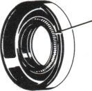
Bearing race elimination from the valve block
HYDORSTATIC TRANSMISSIONS SERVICE,LLC OFFERS VICKERS HYDROSTATIC PARTS AND VICKERS HYDROSTATIC REPAIR
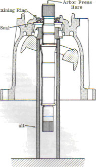
The next steps that involve removing the yoke and front shaft bearing. Look over the yoke for extra wear, scratches and pickup. The yoke could be serviceable if checking the front bearing for brinelling of the rollers and /or roughness, when turned in the race. DO NOT TAKE APART the yoke pintle bearing if the yoke and shaft bearing are not workable. If neither the yoke nor the front shaft bearings are defective, perform the next steps in the order laid out. Removing the drive shaft by installing a nine-inch piece of 1.5” heavy wall tubing over drive shaft within the housing. The end of the tubing will rest next to the inner race of the tapered roller bearing and extend out past the end of the pump housing.
CALL US FOR YOUR REPAIR ON DIFFICULT TO LOCATE HYDRAULIC PUMP,PUMPS MOTOR,MOTORS REPAIR PARTS, AND
MITSUBISHI, KAWASAKI, DAEWOO ,DYNAPOWER, LINDE, REXROTH, UCHIDA, YAMAHA, HITACHI, KOMATSU, LIEBHERR, POCLAIN, VOLVO, VICKERS, CESSNA, HYDROMATIK AND SUNDSTRAND AND EATON CLOSED LOOP AND OPEN LOOP HYDRAULIC PUMPS AND MOTORS PARTS.


Talk to our team of skilled and easygoing specialists. It will be their pleasure to help you.